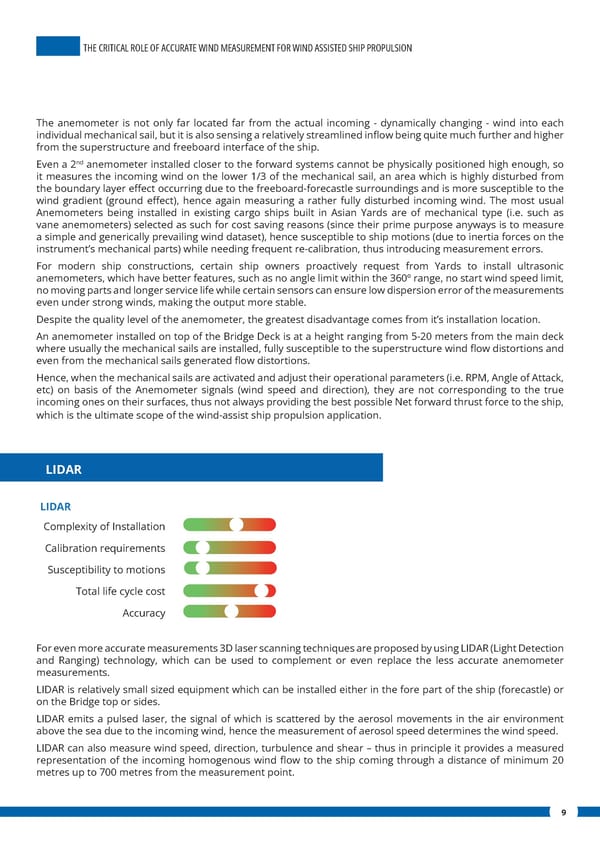
THE CRITICAL ROLE OF ACCURATE WIND MEASUREMENT FOR WIND ASSISTED SHIP PROPULSION WIND MEASUREMENT FOR WIND ASSISTED SHIP PROPULSION The anemometer is not only far located far from the actual incoming - dynamically changing - wind into each individual mechanical sail, but it is also sensing a relatively streamlined in昀氀ow being quite much further and higher from the superstructure and freeboard interface of the ship. nd Even a 2 anemometer installed closer to the forward systems cannot be physically positioned high enough, so it measures the incoming wind on the lower 1/3 of the mechanical sail, an area which is highly disturbed from the boundary layer e昀昀ect occurring due to the freeboard-forecastle surroundings and is more susceptible to the wind gradient (ground e昀昀ect), hence again measuring a rather fully disturbed incoming wind. The most usual Anemometers being installed in existing cargo ships built in Asian Yards are of mechanical type (i.e. such as vane anemometers) selected as such for cost saving reasons (since their prime purpose anyways is to measure a simple and generically prevailing wind dataset), hence susceptible to ship motions (due to inertia forces on the instrument’s mechanical parts) while needing frequent re-calibration, thus introducing measurement errors. For modern ship constructions, certain ship owners proactively request from Yards to install ultrasonic anemometers, which have better features, such as no angle limit within the 360º range, no start wind speed limit, no moving parts and longer service life while certain sensors can ensure low dispersion error of the measurements even under strong winds, making the output more stable. Despite the quality level of the anemometer, the greatest disadvantage comes from it’s installation location. An anemometer installed on top of the Bridge Deck is at a height ranging from 5-20 meters from the main deck where usually the mechanical sails are installed, fully susceptible to the superstructure wind 昀氀ow distortions and even from the mechanical sails generated 昀氀ow distortions. Hence, when the mechanical sails are activated and adjust their operational parameters (i.e. RPM, Angle of Attack, etc) on basis of the Anemometer signals (wind speed and direction), they are not corresponding to the true incoming ones on their surfaces, thus not always providing the best possible Net forward thrust force to the ship, which is the ultimate scope of the wind-assist ship propulsion application. LIDAR LIDAR Complexity of Installation Calibration requirements Susceptibility to motions Total life cycle cost Accuracy For even more accurate measurements 3D laser scanning techniques are proposed by using LIDAR (Light Detection and Ranging) technology, which can be used to complement or even replace the less accurate anemometer measurements. LIDAR is relatively small sized equipment which can be installed either in the fore part of the ship (forecastle) or on the Bridge top or sides. LIDAR emits a pulsed laser, the signal of which is scattered by the aerosol movements in the air environment above the sea due to the incoming wind, hence the measurement of aerosol speed determines the wind speed. LIDAR can also measure wind speed, direction, turbulence and shear – thus in principle it provides a measured representation of the incoming homogenous wind 昀氀ow to the ship coming through a distance of minimum 20 metres up to 700 metres from the measurement point. 9
 The Critical Role of Accurate Wind Measurement for Wind Assisted Ship Propulsion Page 8 Page 10