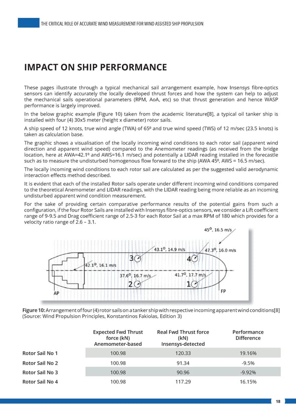
THE CRITICAL ROLE OF ACCURATE WIND MEASUREMENT FOR WIND ASSISTED SHIP PROPULSION IMPACT ON SHIP PERFORMANCE These pages illustrate through a typical mechanical sail arrangement example, how Insensys 昀椀bre-optics sensors can identify accurately the locally developed thrust forces and how the system can help to adjust the mechanical sails operational parameters (RPM, AoA, etc) so that thrust generation and hence WASP performance is largely improved. In the below graphic example (Figure 10) taken from the academic literature[8], a typical oil tanker ship is installed with four (4) 30x5 meter (height x diameter) rotor sails. A ship speed of 12 knots, true wind angle (TWA) of 650 and true wind speed (TWS) of 12 m/sec (23.5 knots) is taken as calculation base. The graphic shows a visualisation of the locally incoming wind conditions to each rotor sail (apparent wind direction and apparent wind speed) compared to the Anemometer readings (as received from the bridge location, here at AWA=42.10 and AWS=16.1 m/sec) and potentially a LIDAR reading installed in the forecastle such as to measure the undisturbed homogenous 昀氀ow forward to the ship (AWA 450, AWS = 16.5 m/sec). The locally incoming wind conditions to each rotor sail are calculated as per the suggested valid aerodynamic interaction e昀昀ects method described. It is evident that each of the installed Rotor sails operate under di昀昀erent incoming wind conditions compared to the theoretical Anemometer and LIDAR readings, with the LIDAR reading being more reliable as an incoming undisturbed apparent wind condition measurement. For the sake of providing certain comparative performance results of the potential gains from such a con昀椀guration, if the four Rotor Sails are installed with Insensys 昀椀bre-optics sensors, we consider a Lift coe昀케cient range of 9-9.5 and Drag coe昀케cient range of 2.5-3 for each Rotor Sail at a max RPM of 180 which provides for a velocity ratio range of 2.6 – 3.1. Figure 10: Arrangement of four (4) rotor sails on a tanker ship with respective incoming apparent wind conditions[8] (Source: Wind Propulsion Principles, Konstantinos Fakiolas, Edition 3) Expected Fwd Thrust Real Fwd Thrust force Performance force (kN) (kN) Di昀昀erence Anemometer-based Insensys-detected Rotor Sail No 1 100.98 120.33 19.16% Rotor Sail No 2 100.98 91.34 -9.5% Rotor Sail No 3 100.98 90.96 -9.92% Rotor Sail No 4 100.98 117.29 16.15% 18
 The Critical Role of Accurate Wind Measurement for Wind Assisted Ship Propulsion Page 17 Page 19