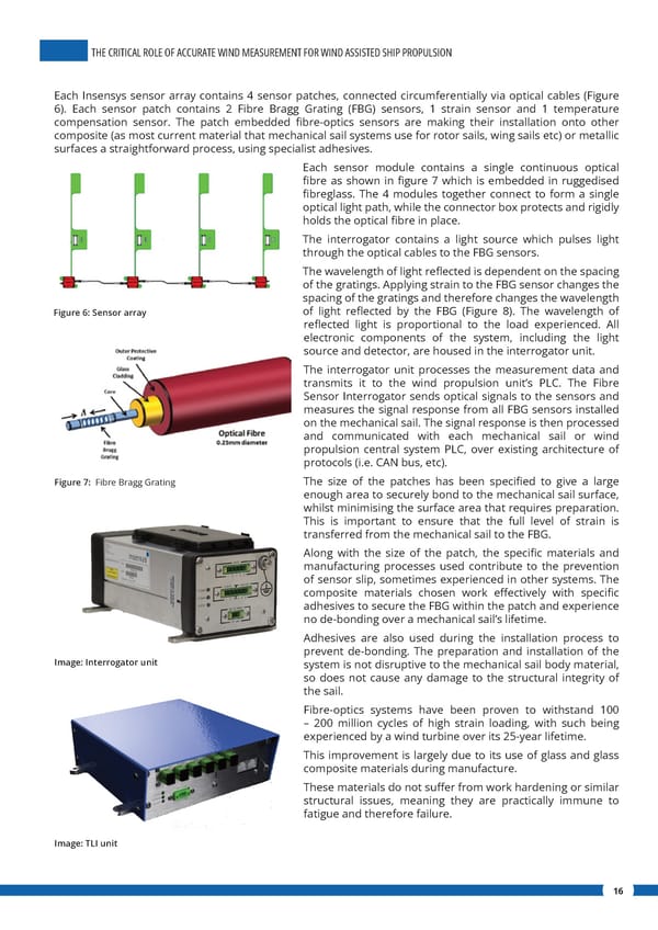
THE CRITICAL ROLE OF ACCURATE WIND MEASUREMENT FOR WIND ASSISTED SHIP PROPULSION Each Insensys sensor array contains 4 sensor patches, connected circumferentially via optical cables (Figure 6). Each sensor patch contains 2 Fibre Bragg Grating (FBG) sensors, 1 strain sensor and 1 temperature compensation sensor. The patch embedded 昀椀bre-optics sensors are making their installation onto other composite (as most current material that mechanical sail systems use for rotor sails, wing sails etc) or metallic surfaces a straightforward process, using specialist adhesives. Each sensor module contains a single continuous optical 昀椀bre as shown in 昀椀gure 7 which is embedded in ruggedised 昀椀breglass. The 4 modules together connect to form a single optical light path, while the connector box protects and rigidly holds the optical 昀椀bre in place. The interrogator contains a light source which pulses light through the optical cables to the FBG sensors. The wavelength of light re昀氀ected is dependent on the spacing of the gratings. Applying strain to the FBG sensor changes the spacing of the gratings and therefore changes the wavelength Figure 6: Sensor array of light re昀氀ected by the FBG (Figure 8). The wavelength of re昀氀ected light is proportional to the load experienced. All electronic components of the system, including the light source and detector, are housed in the interrogator unit. The interrogator unit processes the measurement data and transmits it to the wind propulsion unit’s PLC. The Fibre Sensor Interrogator sends optical signals to the sensors and measures the signal response from all FBG sensors installed on the mechanical sail. The signal response is then processed and communicated with each mechanical sail or wind propulsion central system PLC, over existing architecture of protocols (i.e. CAN bus, etc). Figure 7: Fibre Bragg Grating The size of the patches has been speci昀椀ed to give a large enough area to securely bond to the mechanical sail surface, whilst minimising the surface area that requires preparation. This is important to ensure that the full level of strain is transferred from the mechanical sail to the FBG. Along with the size of the patch, the speci昀椀c materials and manufacturing processes used contribute to the prevention of sensor slip, sometimes experienced in other systems. The composite materials chosen work e昀昀ectively with speci昀椀c adhesives to secure the FBG within the patch and experience no de-bonding over a mechanical sail’s lifetime. Adhesives are also used during the installation process to prevent de-bonding. The preparation and installation of the Image: Interrogator unit system is not disruptive to the mechanical sail body material, so does not cause any damage to the structural integrity of the sail. Fibre-optics systems have been proven to withstand 100 – 200 million cycles of high strain loading, with such being experienced by a wind turbine over its 25-year lifetime. This improvement is largely due to its use of glass and glass composite materials during manufacture. These materials do not su昀昀er from work hardening or similar structural issues, meaning they are practically immune to fatigue and therefore failure. Image: TLI unit 16
 The Critical Role of Accurate Wind Measurement for Wind Assisted Ship Propulsion Page 15 Page 17